|
|
Gonioreflectometer
Cornell University Program of Computer Graphics |
|
||||
A high-quality gonioreflectometer was built by Sing-Choong Foo as
part of his Master's thesis. It was
based on an instrument donated by Kodak.
Sing's thesis includes the most comprehensive documentation of the
intrument, as well as a discussion of design issues and tradeoffs. It
is available as a gzipped PostScript®
file; compressed size is about 1.3MB, expanded size is about 5.5
MB. A PDF file is also available; it is
about 1.9MB.
Source AssemblyThe light source is designed to give a collimated, nonpolarized beam of even irradiance over a large area on the sample.
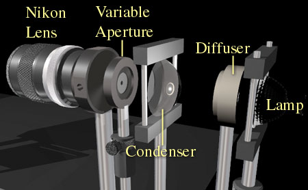
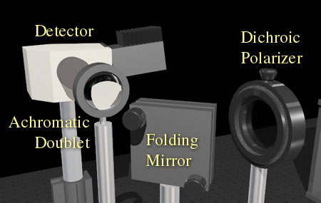
The source is an MR16 quartz-halogen lamp (either ELH, 250W nominal, or FXL, 410W nominal) with integral faceted ellipsoidal reflector. The light is focused on an opal glass diffuser to depolarize it, then collected by an aspheric condenser lens. An adjustable iris aperture is used as a spatial filter to even the illumination; this is placed at the focal plane of a Nikon 135mm camera lens, focused at infinity, which relays the light to the sample. All this is mounted on a 3-foot optical rail which is motorized to rotate across a range of 180 degrees to illuminate the sample from any angle. The source optics are fairly complex in order to meet the goals of good collimation, lack of polarization bias, even illumination across the sample, and high output. DetectorThe light scattered from the sample passes through a dichroic polarizer (Melles-Griot 03 FPG 007), is reflected 90 degrees by a front-surface folding mirror, and is focused onto the detector slit by a 120mm achromatic doublet lens.
An Oriel Multispec spectroradiometer serves as the detector; this contains a 1200 l/mm grating and acquires 1024 samples across the approximate range 385nm-710nm. These results, at a spacing of approximately 0.32 nm per sample, are normally sampled down to 31 points for a resolution of 10nm per sample. This averaging process improves the signal-to-noise ratio of our measurements, and still yields sufficient resolution for physically-based rendering computations. Since the detector uses a diffraction grating to spearate wavelengths, its response varies with polarization. We measure the BRDF twice with polarizations 90 degrees apart, then use a weighted average to get the BRDF for a polarization-insensitive sensor. Motor DrivesThree stepper motors give control of rotational axes of the sample (2 axes) and the light source (1 axis). This allows the measurement of isotropic sample surfaces. Precision and repeatability are on the order of 0.01 degree on each axis.Computer ControlA C++ control program, written by Sing and rewritten by Eric Lafortune, controls the motors, the spectroradiometer, and the power supply for the light source. Data can be acquired almost without human intervention: the software warms up the source in a controlled way, positions the motors for each measurement point, triggers the spectroradiometer, and stores the results. The user need only mount the sample and switch detector polarization when needed (normally once for reference measurements and once for sample measurements).Angular CalibrationThe control software automatically aligns the source and the two sample motors at the start of each session, or whenever desired. To align the source, we remove the sample, rotate the source to aim the source at the detector, and move the arm to scan the source across the detector, measuring at each step. We take the centroid of the resulting measurements as the alignment point for the source: 180 degrees. This is then repeated at finer resolution to confirm and refine the first alignment. To align the sample stage motors, we mount a first-surface mirror in the sample holder, rotate the source arm to 90 degrees, and rotate motor 1 to 45 degrees. This nominally aims the source directly at the sample. We perform a scan alignment by moving motor 1 to scan the source across the detector, then do the same for motor 2. We then repeat the procedure for both motors, using finer steps as in aligning the source arm.Radiometric CalibrationAll measurements are referenced to a direct measurement of the incident beam. We remove the sample from the holder and rotate the source arm to aim the source directly at the detector, then measure the source for each of two polarizations. We measure the spectral reflectance of Spectralon to confirm calibration.Data ProcessingThe control software writes binary data files. We use MATLAB scripts to read, process, and display these files. Processing includes several steps:
| ||||||
| ||||||

